

Servo brake cable selection affects holding safety, motion reliability, and long-term machine uptime. The right cable construction must match brake voltage, current, flexing duty, shielding needs, connector layout, and installation environment. For cwcables customers, choosing the correct servo cable brake pair and motor brake wiring design helps prevent voltage drop, coil overheating, brake release delay, and premature conductor fatigue.
What is servo brake cable,servo cable brake pair, motor brake wiring?
A servo brake cable is the dedicated wiring used to power and control the electromagnetic holding brake inside a servo motor. The servo cable brake pair typically carries DC brake voltage, while motor brake wiring may be integrated into a hybrid servo cable or routed separately depending on the drive, motor, and machine design.
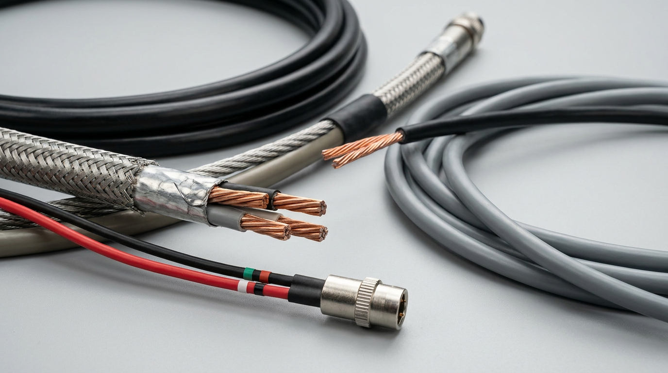
Functional Definition and Cable Role
A servo brake cable connects the servo drive, brake power supply, relay, or safety circuit to the motor’s holding brake coil. When voltage is applied, the brake releases; when voltage is removed, the spring-applied brake engages to hold the motor shaft in position.
In many systems, the brake conductors are built into a larger servo motor cable. In others, they are supplied as a separate servo brake cable for easier service, isolation, or compliance with machine safety architecture.
Based on our internal data and market analysis, here is the breakdown:
| Term | Practical Meaning | Typical Use |
|---|---|---|
| Servo brake cable | Cable dedicated to brake coil power | Separate brake wiring or brake extension |
| Servo cable brake pair | Two conductors inside a servo cable for brake + and brake – | Integrated motor power cable |
| Motor brake wiring | Complete brake circuit from drive or brake supply to motor | Panel wiring, field cable, connector pins |
| Shielded brake pair | Brake conductors with shielding or routed inside shielded cable | Noisy servo environments |
| High-flex brake cable | Brake wiring designed for repeated motion | Robotics, drag chains, gantries |
Correct identification matters because brake wiring is not the same as encoder feedback wiring or motor phase wiring. Brake circuits are usually low-voltage DC but may experience switching noise, inrush current, and repeated mechanical stress.
cwcables Pro Tip: I always confirm whether the brake pair is integrated with the motor power cable or supplied separately before quoting or replacing a servo brake cable. This avoids connector mismatch, incorrect pinout assumptions, and unnecessary machine downtime.
How Does servo brake cable,servo cable brake pair, motor brake wiring Work?
Servo brake wiring works by delivering controlled DC voltage to the motor’s electromagnetic brake coil. When energized, the coil releases the spring-applied brake so the motor can rotate. When power is removed intentionally or during fault conditions, the brake engages and holds the load in position.
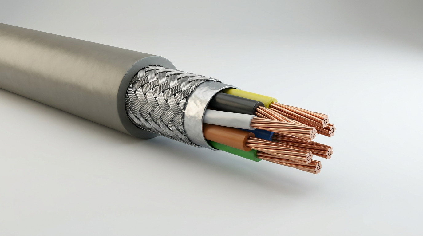
Brake Release and Holding Sequence
A servo motor brake is usually a holding brake, not a dynamic stopping brake. Its main job is to hold vertical axes, prevent drift, and secure loads when the servo drive is disabled.
A typical operating sequence is:
- The control system enables the servo drive.
- The brake output or external relay applies DC voltage to the brake coil.
- The brake coil magnetically releases the mechanical brake.
- The drive begins commanding motor motion after a short release delay.
- When stopping, the drive decelerates the motor first.
- Brake voltage is removed only after the motor reaches a safe stop or holding condition.
- The spring mechanism engages and locks the shaft.
Important design points include voltage drop, release timing, relay contact rating, and cable flex life. If the servo cable brake pair has undersized conductors, long cable runs can reduce voltage at the brake coil and cause incomplete release, heat buildup, or brake wear.
Based on our internal data and market analysis, here is the breakdown:
| Parameter | Why It Matters | Common Check |
|---|---|---|
| Brake voltage | Must match motor brake coil rating | 24 VDC is common, but not universal |
| Brake current | Determines conductor size and relay rating | Check holding and inrush current |
| Cable length | Affects voltage drop | Calculate voltage at motor end |
| Release delay | Prevents motor fighting locked brake | Verify timing in drive parameters |
| Shielding | Reduces EMI coupling | Important near motor phase conductors |
cwcables Pro Tip: I recommend checking voltage directly at the motor brake pins during release, not only at the cabinet power supply. Long runs, small conductors, or oxidized contacts can make the brake look electrically correct at the panel but weak at the motor.
What are the benefits of servo brake cable,servo cable brake pair, motor brake wiring?
A properly designed servo brake cable improves holding safety, reduces nuisance faults, protects brake coils, and supports stable motion control. Correct servo cable brake pair construction also helps minimize EMI issues, simplify installation, and extend service life in moving applications such as gantries, robots, packaging machines, and CNC equipment.
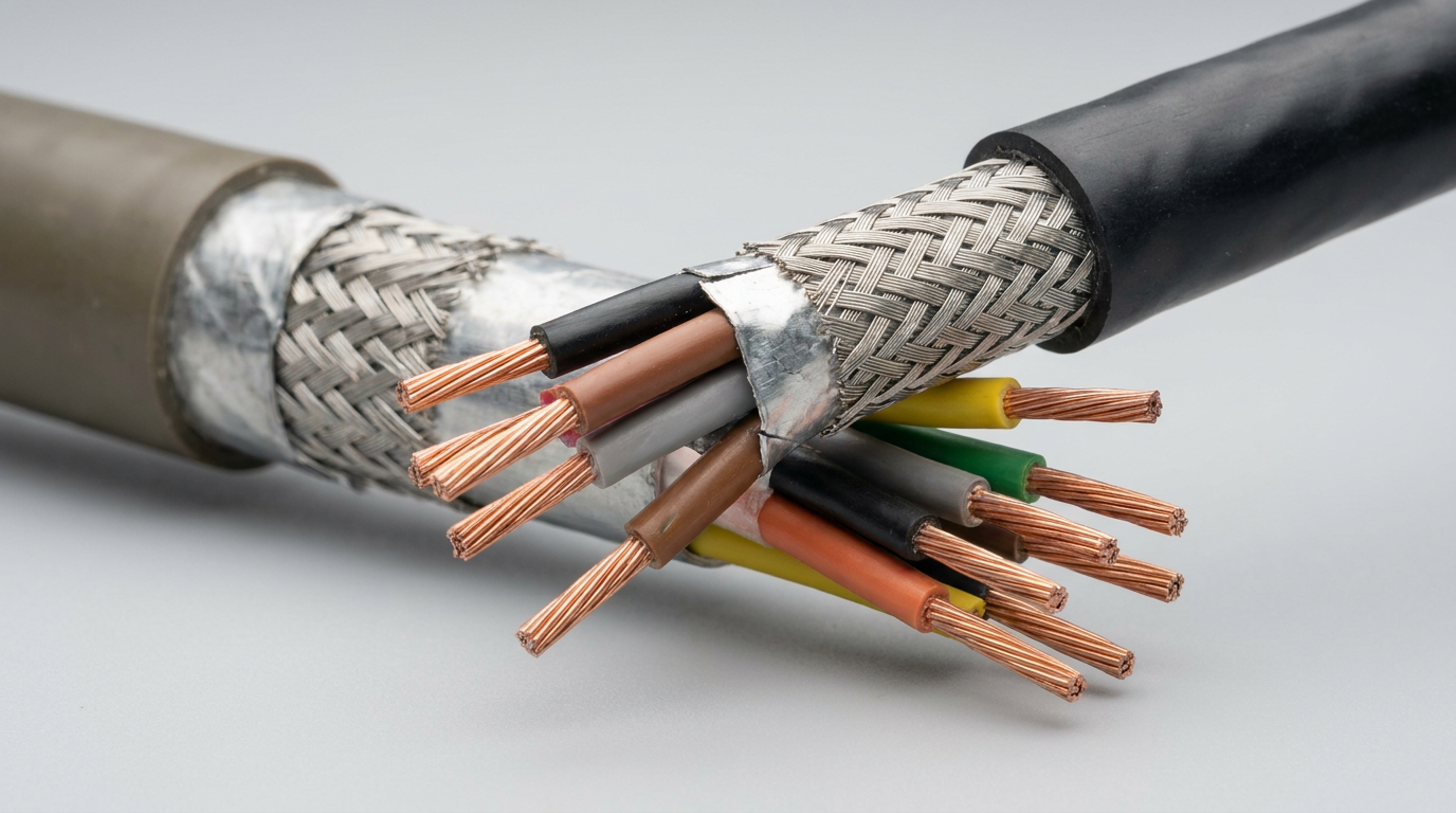
Performance, Safety, and Reliability Benefits
Brake wiring is often overlooked because it uses fewer conductors than power or feedback cables. However, its impact is significant. A weak, intermittent, or incorrectly wired brake circuit can cause axis drop, motor alarms, unexpected load movement, or accelerated brake wear.
Key benefits include:
- Safer load holding: Proper motor brake wiring helps keep vertical and gravity-loaded axes secure.
- Reliable brake release: Correct conductor size reduces voltage drop and incomplete release.
- Lower heat stress: Stable voltage prevents coil overheating caused by poor contact or partial energization.
- Reduced downtime: Durable cable jackets and high-flex conductors survive repeated motion.
- Cleaner installation: Integrated servo cable brake pair designs reduce cable clutter.
- Better EMI control: Shielding and correct routing reduce interference with feedback and control signals.
Based on our internal data and market analysis, here is the breakdown:
| Benefit | Cable Design Factor | Result |
|---|---|---|
| Holding safety | Correct pinout and brake voltage | Secure load retention |
| Longer brake life | Stable release voltage | Less mechanical dragging |
| Fewer alarms | Reliable continuity | Reduced brake or drive faults |
| Easier maintenance | Clear conductor marking | Faster troubleshooting |
| Motion durability | High-flex copper and PUR jacket | Longer drag-chain life |
cwcables Pro Tip: I treat brake wiring as a safety-related function in practical machine design, even when it is not part of a certified safety circuit. A small cable choice can have a large effect on whether a load stays exactly where it should.
How to maintain a servo brake cable,servo cable brake pair, motor brake wiring?
Maintain servo brake cable systems by inspecting jacket wear, connector tightness, continuity, insulation resistance, brake voltage, and flex-zone routing. Preventive checks are especially important in drag chains, robotic arms, and vertical axes where a failing servo cable brake pair can cause intermittent release or unsafe holding behavior.
Inspection and Preventive Maintenance Checklist
Maintenance should combine visual inspection, electrical testing, and operating observation. Brake cable failures often begin as intermittent faults caused by conductor fatigue, oil ingress, loose connector pins, or repeated bending below the recommended radius.
Use this maintenance process:
- Lock out and verify safety conditions before touching motor brake wiring.
- Inspect the cable jacket for cuts, flattening, oil swelling, abrasion, or cracking.
- Check connector shells and strain reliefs for looseness or damage.
- Verify brake voltage at the motor end during commanded release.
- Measure continuity of the brake pair while gently flexing the cable.
- Check insulation resistance if moisture, coolant, or oil exposure is suspected.
- Confirm drag-chain routing with no twisting, pinching, or forced bend radius.
- Review brake timing parameters after replacing motors, drives, or cables.
Based on our internal data and market analysis, here is the breakdown:
| Maintenance Item | Recommended Focus | Warning Sign |
|---|---|---|
| Jacket condition | Abrasion and chemical exposure | Swelling, cuts, cracks |
| Connector pins | Fit, corrosion, retention | Intermittent brake release |
| Voltage test | Motor-end brake voltage | Slow or incomplete release |
| Flex test | Continuity during movement | Faults at certain positions |
| Routing | Bend radius and strain relief | Broken conductors near ends |
cwcables Pro Tip: I never judge a brake cable only by static continuity. If the machine fault happens during motion, flex the cable through its real working path while testing the brake pair—many failures only appear under movement.
What is the price of servo brake cable,servo cable brake pair, motor brake wiring?
The price of a servo brake cable depends on conductor size, cable length, shielding, jacket material, flex rating, connector type, certification, and whether the brake pair is supplied alone or integrated into a complete servo motor cable assembly. Custom cwcables solutions are priced by application requirements and build complexity.
Pricing Variables and Typical Cost Drivers
Servo brake cable pricing is not determined only by length. A short high-flex cable with molded connectors and industrial approvals may cost more than a longer simple static cable. For accurate pricing, the motor model, drive model, pinout, environment, and motion requirements should be confirmed first.
Based on our internal data and market analysis, here is the breakdown:
| Cost Factor | Lower-Cost Option | Higher-Cost Option |
|---|---|---|
| Construction | Separate 2-core brake cable | Hybrid servo cable with brake pair |
| Flex rating | Static or occasional movement | Continuous drag-chain flex |
| Shielding | Unshielded brake pair | Overall shield or individually shielded pair |
| Jacket | PVC | PUR, TPE, oil-resistant compounds |
| Connectors | Open-end leads | Circular connectors, molded plugs |
| Certification | Standard industrial cable | UL, CE, CSA, or application-specific compliance |
| Quantity | Single replacement | Batch production with optimized unit cost |
To estimate budget, consider these buying questions:
- What is the brake voltage and current?
- Is the cable moving continuously or installed statically?
- Is shielding required due to nearby motor phase wiring?
- Does the cable need oil, coolant, UV, or abrasion resistance?
- Are molded connectors required, or are open-end leads acceptable?
- Is the pinout OEM-standard or custom?
cwcables Pro Tip: I ask for a photo of the nameplate, connector face, and existing cable markings before pricing replacements. Those details often reveal the exact brake pair layout, shielding structure, and connector family faster than a part number alone.
Key Features & Comparison
The best servo brake cable construction balances electrical capacity, mechanical durability, EMI protection, and connector compatibility. For most industrial applications, the right choice depends on whether the motor brake wiring is static, repeatedly flexed, exposed to oil, routed near power conductors, or integrated into a complete servo cable assembly.
Construction Options Compared
Based on our internal data and market analysis, here is the breakdown:
| Feature | Basic Brake Cable | Shielded Brake Pair | High-Flex Brake Cable | Hybrid Servo Cable with Brake Pair |
|---|---|---|---|---|
| Best Use | Static cabinet-to-motor wiring | Noisy electrical environments | Drag chains and moving axes | Compact servo motor connections |
| Conductors | Usually 2 cores | 2 cores with shield or inside shielded cable | Fine-strand copper | Power, brake, and sometimes feedback elements |
| EMI Protection | Low to moderate | High | Moderate to high | High when properly shielded |
| Flex Life | Limited | Depends on construction | High | Varies by cable design |
| Installation Simplicity | Simple | Moderate | Moderate | High cable consolidation |
| Maintenance Access | Easy to isolate | Easy if separate | Easy if separate | More integrated, less separation |
| Typical Jacket | PVC | PVC or PUR | PUR or TPE | PUR, TPE, or special compounds |
| Cost Level | Low | Medium | Medium to high | Higher but cleaner installation |
Feature selection should follow the actual machine environment rather than a generic preference. For example, a static motor brake cable inside a protected panel does not need the same construction as a continuously flexing brake pair in a three-axis gantry. Conversely, using a low-flex cable in a drag chain can cause early conductor fatigue even when the electrical rating appears correct.
Recommended selection priorities:
- Match brake voltage and current first.
- Confirm connector pinout and polarity.
- Choose conductor size based on current and cable length.
- Select shielding according to EMI exposure.
- Match jacket material to oil, coolant, abrasion, and temperature.
- Specify high-flex construction for moving cable carriers.
cwcables Pro Tip: I prefer specifying the cable by application conditions, not just by conductor count. “2-core brake cable” is incomplete; “2-core shielded PUR high-flex brake pair for drag-chain servo use” gives engineering and purchasing teams a much safer target.
Cost & Buying Factors
When buying servo brake cable, prioritize compatibility and lifecycle cost over the lowest unit price. The right motor brake wiring should match brake coil demand, cable motion class, connector standard, environmental exposure, and maintenance strategy. A slightly better cable often prevents far more expensive servo downtime later.
Practical Buying Guide
The best purchase decision starts with technical confirmation. If any detail is uncertain, the cable supplier should verify the application before production or replacement. This is especially important for imported servo motors, older systems, and machines with modified wiring.
Use this buying checklist:
- Motor and drive information: Brand, model number, brake voltage, and brake current.
- Cable length: Total route length, including cabinet, cable carrier, and service loops.
- Motion requirement: Static, occasional flex, continuous flex, torsion, or robotic movement.
- Connector requirement: Open-end, solder, crimp, molded connector, or OEM-compatible plug.
- Shielding requirement: Unshielded, overall shield, foil shield, braid shield, or hybrid shielding.
- Environment: Oil, coolant, weld spatter, UV, washdown, heat, abrasion, or outdoor exposure.
- Compliance: UL, CE, RoHS, halogen-free, flame-retardant, or customer-specific standards.
Based on our internal data and market analysis, here is the breakdown:
| Buying Factor | Why It Affects Cost | Recommended Decision |
|---|---|---|
| Length | More copper and jacket material | Avoid excessive length but allow service loops |
| Flex class | Requires finer conductors and stronger jacket | Choose high-flex for moving axes |
| Connector style | Labor and component cost vary widely | Match OEM fit and pinout exactly |
| Shielding | Adds materials and termination labor | Use when routed near power or feedback cables |
| Jacket compound | Determines chemical and wear resistance | Select PUR/TPE for harsh motion environments |
| Custom pinout | Requires engineering verification | Provide drawings or samples when possible |
A reliable quotation should include cable structure, conductor size, jacket material, shielding, length, connector type, pinout, and testing requirements. cwcables can support custom assemblies when standard parts do not fit the machine layout.
cwcables Pro Tip: I recommend buying one verified sample before ordering a large batch for mixed servo platforms. Once the sample confirms fit, brake release, and routing performance, scaling production becomes much safer.
Conclusion
Choosing the correct servo brake cable is essential for safe holding, reliable brake release, and stable machine operation. By matching the servo cable brake pair to voltage, current, flexing, shielding, connector, and environmental requirements, engineers can reduce downtime and improve long-term servo system reliability.
Final Selection Guidance
A servo brake cable may look simple, but it performs a critical function. The brake pair must energize consistently, survive the installation environment, and maintain continuity through the full motion cycle of the machine.
For best results, confirm these points before purchasing:
- Brake voltage and current rating.
- Cable length and voltage drop.
- Static, flexing, or torsion movement.
- Shielding and EMI exposure.
- Connector family, pinout, and polarity.
- Jacket resistance to oil, coolant, abrasion, and heat.
- Testing requirements for continuity, insulation, and final assembly.
Based on our internal data and market analysis, here is the breakdown:
| Decision Area | Best Practice |
|---|---|
| Safety | Treat brake wiring as critical to load holding |
| Electrical design | Size conductors for current and voltage drop |
| Mechanical design | Use high-flex construction in moving applications |
| EMI control | Apply shielding where brake wiring runs near servo power |
| Procurement | Provide motor, drive, connector, and pinout details |
| Maintenance | Inspect and test brake wiring during scheduled service |
cwcables Pro Tip: If you are unsure which servo brake cable construction fits your machine, send cwcables the motor model, cable length, connector photos, and motion environment. I can help narrow the design quickly and avoid costly trial-and-error replacements.