

Encoder cable maximum length is not a fixed number; it depends on signal type, cable construction, electrical noise, encoder output strength, receiving electronics, and installation quality. When encoder cable distance increases, voltage drop, capacitance, impedance mismatch, and electromagnetic interference can reduce encoder signal integrity. Choosing the right cable, shielding, grounding, and differential signaling is the key to reliable long-distance feedback.
What is encoder cable maximum length?
Encoder cable maximum length is the longest practical cable run that can carry encoder signals without causing missed pulses, timing errors, noise distortion, or communication faults. In real applications, the limit depends on encoder output type, pulse frequency, voltage level, cable capacitance, shielding, grounding, and the electrical environment around the machine.
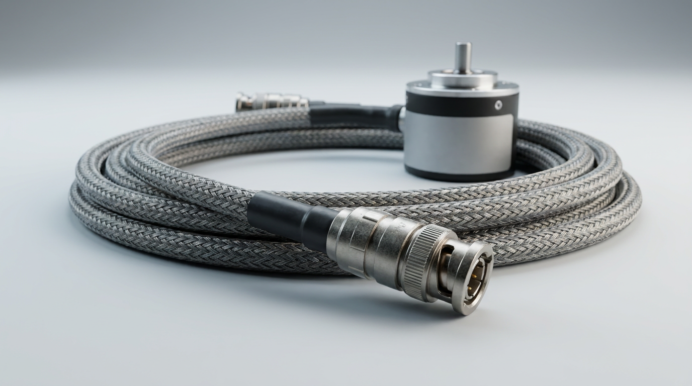
Practical Definition and Typical Distance Ranges
Encoder cable maximum length should be treated as an engineering limit, not a universal specification. A cable that works at 5 meters in a clean lab may fail at 20 meters beside a VFD, servo drive, welding machine, or high-current motor cable.
Based on our internal data and market analysis, here is the breakdown:
| Encoder Signal Type | Typical Reliable Distance | Signal Robustness | Common Use Case |
|---|---|---|---|
| Single-ended TTL / Push-pull | 3–10 m | Low to moderate | Short machine wiring, compact equipment |
| Open collector | 5–15 m | Moderate, speed-dependent | Industrial sensors, lower-speed feedback |
| Differential line driver / RS-422 | 30–100 m+ | High | Servo motors, CNC, motion control |
| Sin/Cos analog encoder | 10–50 m | Sensitive to noise and attenuation | Precision feedback systems |
| Absolute encoder with serial protocol | 20–100 m+ | Protocol-dependent | Robotics, automation, position systems |
The most important point is that maximum distance decreases as encoder frequency increases. A slow encoder output can travel farther than a high-resolution encoder running at high RPM because fast pulse edges are more vulnerable to cable capacitance and signal distortion.
cwcables Pro Tip: I always confirm encoder output type first. If the encoder is single-ended and the cable run is long, upgrading to a differential line-driver encoder cable is usually more effective than simply using a thicker cable.
How Does encoder cable maximum length Work?
Encoder cable maximum length works by balancing signal strength against losses and interference along the cable. As distance increases, cable resistance, capacitance, and external noise degrade pulse shape and timing. Once the receiver can no longer clearly distinguish high and low states, encoder signal integrity becomes unreliable.
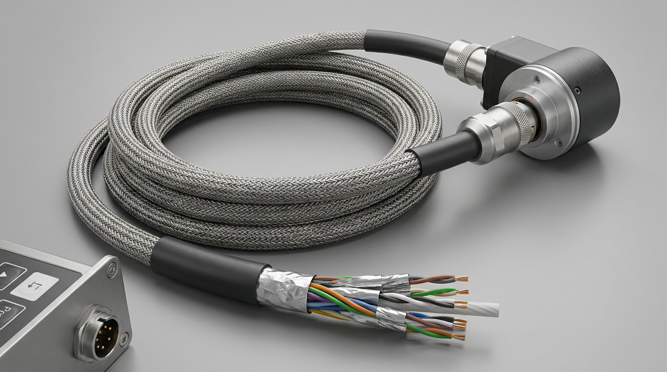
Signal Degradation Over Distance
An encoder sends position information as pulses, analog waveforms, or digital communication data. The cable must preserve both voltage level and timing accuracy. Long cable runs affect both.
Key mechanisms that limit encoder cable distance include:
- Voltage drop
Longer conductors add resistance, reducing the voltage available at the receiver and sometimes at the encoder itself. - Cable capacitance
Capacitance slows pulse edges, turning sharp square waves into rounded signals that can cause missed counts. - Electromagnetic interference
Nearby power cables, motors, relays, and drives can inject noise into encoder lines. - Impedance mismatch
Poor cable selection or incorrect termination can create reflections, especially with fast digital signals. - Ground potential differences
Long machine runs can develop different ground references, creating unwanted current in shields or signal returns. - High pulse frequency
Higher resolution and higher RPM create faster signal transitions, reducing the allowable cable length.
Differential signaling improves reliability because the receiver compares two opposite signals instead of measuring one signal against ground. This cancels common-mode noise and allows much longer encoder cable distance.
cwcables Pro Tip: I never route encoder cables in the same tray as motor power leads unless separation is impossible. If they must cross, I cross them at 90 degrees to reduce induced noise.
What are the benefits of encoder cable maximum length?
Understanding encoder cable maximum length helps prevent feedback errors, motion instability, machine downtime, and difficult troubleshooting. It allows engineers to select the right cable, signal format, shielding, and routing method before installation, improving encoder signal integrity across short, medium, and long-distance automation systems.
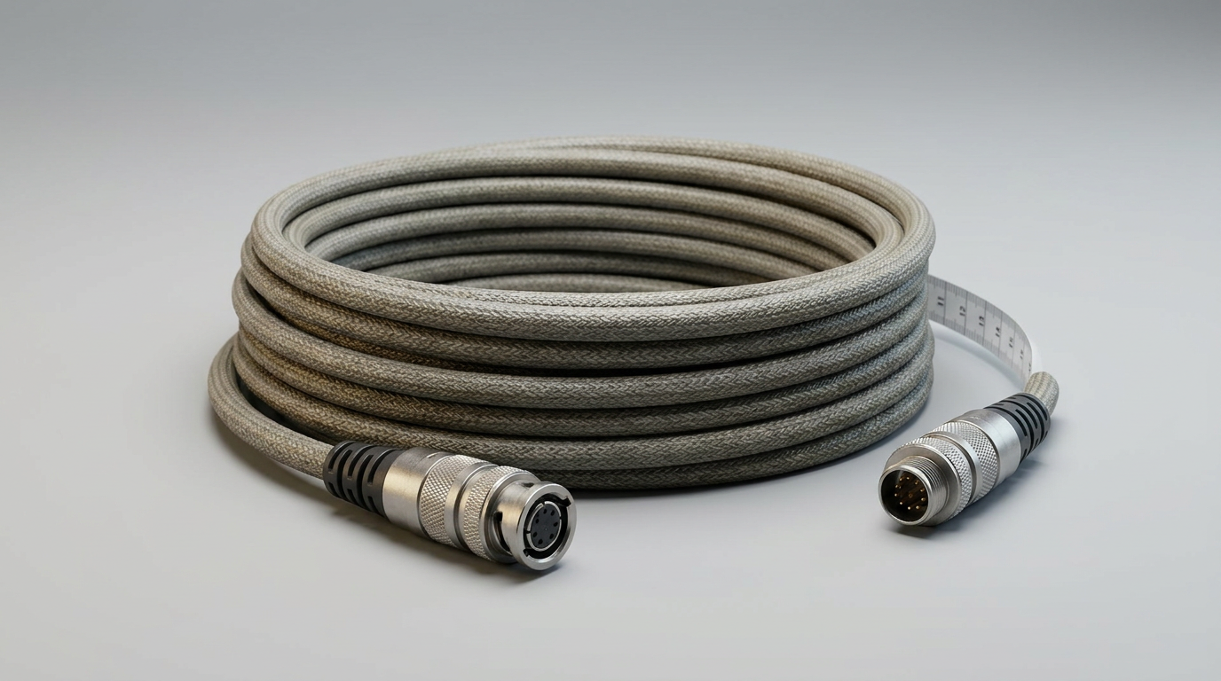
Why Length Planning Improves System Reliability
Correctly planning encoder cable distance provides both technical and economic benefits. It reduces trial-and-error commissioning, prevents intermittent faults, and protects the control system from feedback instability.
Main benefits include:
- Fewer missed pulses because signal levels remain within receiver thresholds.
- Improved motion accuracy for servo, CNC, robotic, and positioning systems.
- Lower electrical noise risk through proper shielding and pair twisting.
- Reduced downtime caused by random encoder faults.
- Cleaner installation design because cable routing and termination are planned early.
- Longer component life by avoiding ground-loop and noise-related stress.
- Better scalability when future machine expansions require longer encoder runs.
For high-performance systems, encoder cable maximum length is directly tied to feedback quality. A motor drive can only control motion accurately if it receives clean, stable, correctly timed encoder information.
cwcables Pro Tip: I recommend designing for margin. If an application needs 30 meters, do not choose a setup that barely works at 30 meters in ideal conditions. Select cable and signaling that can reliably support more than the required distance.
How to maintain a encoder cable maximum length?
Maintaining reliable encoder cable maximum length requires preserving cable shielding, grounding, routing, connector quality, and signal terminations throughout the machine’s life. Regular inspection helps prevent intermittent faults caused by vibration, abrasion, moisture, loose connectors, shield damage, or changes in nearby electrical equipment.
Maintenance Checklist for Long Encoder Runs
Encoder cable reliability is not only determined at installation. Cable movement, machine vibration, oil exposure, bending stress, and electrical upgrades can all reduce encoder signal integrity over time.
Use this maintenance checklist:
- Inspect the cable jacket
Look for cuts, crushing, kinks, abrasion, oil swelling, or heat damage. - Check connector locking
Loose M12, D-sub, circular, or terminal connections can create intermittent signal loss. - Verify shield continuity
A broken shield greatly reduces noise protection, especially over long encoder cable distance. - Confirm grounding method
Avoid accidental shield grounding changes that can create ground loops. - Measure supply voltage at the encoder
Long runs may cause voltage drop, especially under load. - Review routing after machine changes
New VFDs, power cables, solenoids, or welding equipment can introduce additional interference. - Check termination resistors
Differential signals may require correct termination to prevent reflections. - Use an oscilloscope for critical systems
Check pulse shape, noise level, and edge clarity at the receiver end.
A system that worked for years can become unreliable after a cable is rerouted, a shield is disconnected, or new high-power equipment is installed nearby.
cwcables Pro Tip: When troubleshooting, I check the encoder waveform at the controller, not only at the encoder. The controller-end signal shows what the drive or PLC actually receives after the full cable run.
What is the price of encoder cable maximum length?
The price of achieving a reliable encoder cable maximum length depends on cable length, conductor count, shielding design, connector type, jacket material, flexibility rating, and whether the signal requires differential pairs. Longer, high-flex, oil-resistant, shielded encoder cables cost more but usually reduce downtime and signal failures.
Pricing Factors for Reliable Encoder Cable Distance
There is no single price for encoder cable maximum length because the “maximum length” is achieved through the complete cable design. A low-cost unshielded cable may appear cheaper but can fail in electrically noisy environments.
Based on our internal data and market analysis, here is the breakdown:
| Cost Factor | Price Impact | Why It Matters |
|---|---|---|
| Cable length | High | More copper, shielding, jacket material, and assembly time |
| Shielding type | Medium to high | Foil, braid, or combined shields improve encoder signal integrity |
| Twisted pair construction | Medium | Reduces noise and supports differential signals |
| Connector type | Medium | Industrial circular connectors cost more than basic terminals |
| High-flex rating | High | Required for drag chains, robotics, and moving axes |
| Jacket material | Medium | PUR, TPE, or oil-resistant jackets cost more than basic PVC |
| Custom pinout | Medium | Ensures compatibility with encoder, drive, or controller |
For many industrial systems, paying more for the correct cable is less expensive than losing production time due to random encoder alarms, position drift, or servo instability.
cwcables Pro Tip: I look at total cost, not cable price alone. A properly shielded custom encoder cable from cwcables can prevent hours of troubleshooting, which often costs far more than the cable itself.
Key Features & Comparison
The best encoder cable for long-distance reliability combines low capacitance, twisted signal pairs, strong shielding, correct impedance, durable insulation, and secure connectors. Comparing cable types helps determine whether a basic cable is sufficient or whether a purpose-built industrial encoder cable is required for stable signal transmission.
Feature Comparison for Encoder Signal Integrity
Based on our internal data and market analysis, here is the breakdown:
| Feature | Basic Control Cable | Standard Shielded Encoder Cable | High-Performance Differential Encoder Cable |
|---|---|---|---|
| Recommended distance | Short | Short to medium | Medium to long |
| Shielding | None or minimal | Foil or braid shield | Foil + braid, optimized coverage |
| Pair twisting | Often absent | Usually included | Precision twisted pairs |
| Noise resistance | Low | Good | Excellent |
| High-speed pulse support | Limited | Moderate | Strong |
| Flexibility options | Limited | Available | High-flex and drag-chain options |
| Best environment | Clean electrical panels | General machinery | Servo, CNC, robotics, VFD-heavy areas |
| Typical risk | Noise, pulse loss | Moderate installation sensitivity | Lower risk when installed correctly |
For demanding applications, differential encoder cables are usually the best choice. They are designed to preserve pulse symmetry, reduce electromagnetic pickup, and maintain reliable communication over longer runs.
Important features to prioritize include:
- Low capacitance per meter
- Individually twisted signal pairs
- Overall braided or foil shield
- Correct conductor gauge for voltage drop control
- Oil-resistant or high-flex jacket when required
- Connector strain relief and secure locking
- Compatibility with encoder output and controller input
cwcables Pro Tip: I always match the cable to the signal, not just the connector. Two cables may plug in the same way, but only one may have the shielding and pair structure needed for long encoder cable distance.
Cost & Buying Factors
When buying for encoder cable maximum length, evaluate the complete application: distance, encoder type, pulse frequency, environment, motion, connector style, and controller requirements. The right cable should provide enough electrical margin for reliable operation rather than simply meeting the lowest upfront price.
Buying Guide for Long Encoder Cable Runs
A good purchasing decision starts with technical requirements. Before ordering, confirm the installation details and choose a cable assembly designed for the actual operating conditions.
Use this buying checklist:
- Confirm encoder output type
Identify whether the signal is single-ended, push-pull, open collector, differential, analog, or serial. - Calculate required encoder cable distance
Include routing path, service loops, cabinet entry, and moving-axis travel. - Check pulse frequency
Higher resolution and faster shaft speed require better cable performance. - Evaluate electrical noise
Drives, motors, welding systems, pumps, and high-current cables increase shielding requirements. - Choose the correct shielding
Use foil, braid, or combined shielding depending on noise severity. - Select jacket material
PVC may work for static indoor use; PUR or TPE is better for oil, abrasion, and flexing. - Specify connectors and pinout
Ensure compatibility with the encoder, motor feedback port, PLC, or servo drive. - Plan for installation margin
Avoid running near the maximum distance without safety margin.
The best cable is not always the most expensive one. It is the one that matches the signal, environment, and mechanical duty cycle with enough reliability margin.
cwcables Pro Tip: When customers ask for help, I request encoder model, controller model, cable length, and routing environment first. With those details, cwcables can recommend a cable that fits both performance and budget.
Conclusion
Encoder cable maximum length is controlled by signal type, cable quality, noise exposure, grounding, shielding, and installation practice. Reliable long-distance encoder performance requires more than adding cable length; it requires protecting waveform quality from the encoder to the controller under real operating conditions.
Final Recommendations for Reliable Encoder Cable Distance
For dependable encoder signal integrity, treat the cable as part of the feedback system. A high-quality encoder and controller can still perform poorly if the cable introduces noise, voltage drop, or timing distortion.
Best practices include:
- Use differential signaling for longer cable runs whenever possible.
- Choose shielded, twisted-pair encoder cable for industrial environments.
- Keep encoder cables away from motor power and VFD cables.
- Maintain proper grounding and shield termination.
- Verify cable capacitance, voltage drop, and connector compatibility.
- Test critical systems at the controller end under real machine conditions.
- Build in distance margin instead of operating at the edge of reliability.
If you need help selecting an encoder cable for a specific distance, signal type, or machine environment, cwcables can support custom cable assemblies designed for reliable encoder performance.
cwcables Pro Tip: My final rule is simple: long encoder runs need engineered cables, not guesswork. If the feedback signal matters to machine accuracy, choose the cable with the same care as the encoder itself.